Understanding RSTP Through Configuration
- Cisco製品はデフォルトコンフィグでも(R)STPが動作する
-
それでも、STPのコンフィグを行えると利点がある
- 所望のswitchをSTP root switchに選出させることができるなどの利点がある
The Need for Multiple Spanning Trees
- VLANの出現前までは CST: common spanning tree トポロジーを考えればよかった
- VLANの登場により、負荷分散の検知から、同一の物理接続上で複数の論理的なspanning treeを考えるべきになった
STP Modes and Standards
Switch>enable
Switch#configure terminal
Enter configuration commands, one per line.  End with CNTL/Z.
Switch(config)#spanning-tree mode ?
  pvst        Per-Vlan spanning tree mode
  rapid-pvst  Per-Vlan rapid spanning tree mode
Switch(config)#spanning-tree mode
種類
| Name | Base | # Trees | Original IEEE Standard | Config Parameter |
|---|---|---|---|---|
| STP | STP | 1 (CST) | 802.1D | |
| PVST+ | STP | 1/VLAN | 802.1D | pvst |
| RSTP | RSTP | 1 (CST) | 802.1w | |
| Rapid PVST | RSTP | 1/VLAN | 802.1w | rapid-pvst |
| MSTP | RSTP | 1 or more | 802.1s | mst |
- Packet Tracerではmstは無かった
-
MSTI: Multi Spanning Tree Instances
- 複数のSTを選べるが、VLANごとに1つを要求するものではない
SW2#show spanning-tree vlan 1
VLAN0001
  Spanning tree enabled protocol rstp
  Root ID    Priority    24577
             Address     0090.0CA7.83C1
             This bridge is the root
             Hello Time  2 sec  Max Age 20 sec  Forward Delay 15 sec

  Bridge ID  Priority    24577  (priority 24576 sys-id-ext 1)
             Address     0090.0CA7.83C1
             Hello Time  2 sec  Max Age 20 sec  Forward Delay 15 sec
             Aging Time  20

Interface        Role Sts Cost      Prio.Nbr Type
---------------- ---- --- --------- -------- --------------------------------
Fa0/11           Desg BLK 19        128.11   P2p
Gi0/1            Desg BLK 4         128.25   P2p
Gi0/2            Desg BLK 4         128.26   P2p

SW2#- これ:
Spanning tree enabled protocol rstpThe Bridge ID and System ID Extension
-
per-VLANであれMSTであれ、複数のSpanning Treeを扱うとなると、VLANとVLAN trunkingを考える必要が出てくる
- ゆえに、現在ではRSTPとMSTPは802.1Q標準の一部
- VLAN taggingの標準
-
BIDを拡張する
- Priority 2バイト(16ビット)の内訳
- 上位4ビット: priority
-
下位12ビット: System ID Extension
- 典型的にはVLANのID(12bit)を格納する
Switch#show spanning-tree vlan 1
VLAN0001
  Spanning tree enabled protocol ieee
  Root ID    Priority    32769
             Address     0001.428C.987C
             Cost        4
             Port        25(GigabitEthernet0/1)
             Hello Time  2 sec  Max Age 20 sec  Forward Delay 15 sec

  Bridge ID  Priority    32769  (priority 32768 sys-id-ext 1)
             Address     0030.A396.EE00
             Hello Time  2 sec  Max Age 20 sec  Forward Delay 15 sec
             Aging Time  20

Interface        Role Sts Cost      Prio.Nbr Type
---------------- ---- --- --------- -------- --------------------------------
Fa0/11           Desg FWD 19        128.11   P2p
Gi0/1            Root FWD 4         128.25   P2p
Gi0/2            Desg FWD 4         128.26   P2p

Switch#
Bridge ID Priority 32769 (priority 32768 sys-id-ext 1)- こうした経緯により、priorityには4096(2^12)の倍数しか設定できない
Switch(config)#spanning-tree vlan 1 priority ?
<0-61440> bridge priority in increments of 4096- 数値を直接指定するのではなく、便利なエイリアスがある
-
root primary- 24576 (32768 - 8192)
- デフォルト値32768よりも小さい = 優先される
Switch#show spanning-tree vlan 1
VLAN0001
  Spanning tree enabled protocol ieee
  Root ID    Priority    24577
...-
root secondary- 28672 (32768 - 4096)
- デフォルト値32768よりも小さい = 優先される
- primaryよりは大きい = 優先されない
Switch(config)#spanning-tree vlan 1 root secondary
Switch(config)#end
Switch#show spanning-tree vlan 1
VLAN0001
  Spanning tree enabled protocol ieee
  Root ID    Priority    28673
...-
root primaryは、現rootが24576以下をすでに使用していれば、4096を用いることになっているらしい- 【補】Packet Tracerでは、rootを24576にして試したら、20480になった
How Switches Use the Priority and System ID Extension
SW2#configure terminal
Enter configuration commands, one per line.  End with CNTL/Z.
SW2(config)#spanning-tree vlan 1 priority 24576
SW2(config)#end
SW2#
SW2#show spanning-tree vlan 1
VLAN0001
Spanning tree enabled protocol ieee
Root ID Priority 24577
...- 抜粋
...
SW2(config)#spanning-tree vlan 1 priority 24576
...
  Root ID    Priority    24577
...
24577 = 0b(0110 | 0000 0000 0001)- VLAN IDが12bitなので単純足し算
RSTP Methods to Support Multiple Spanning Trees
- IEEE標準のRSTPとCisco独自のRPVST+の違い
| RSTP | RPVST+ | |
|---|---|---|
| # tree | 1 (CST) | 1 / VLAN |
| # message / network | 1 | 1 / VLAN |
| Destination MAC Address (multicast) | 0180.C200.0000 |
0100.0CCC.CCCD |
| VLAN tagging (802.1Q header) | なし | あり |
| extra TLV: type-length value | なし | あり (VLAN IDの識別用) |
| 12-bit System ID Extension部分の解釈 | VLANなし | VLAN ID |
Other RSTP Configuration Options
-
Switch Priority
spanning-tree vlan x priority y
-
Primary and Secondary Root Switches
spanning-tree vlan x root (primary|secondary)
-
Port Costs
spanning-tree [vlan x] cost y- Packet Tracerには無さげ
Configuring Layer 2 EtherChannel
-
複数のinterfaceを論理的にまとめるやつ
- すべてをパラレルに用いる
- 負荷分散
- 障害時のSTP convergenceの回避
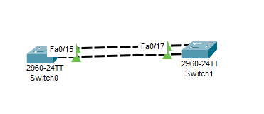
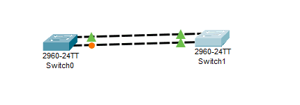
Configuring a Manual Layer 2 EtherChannel
- これになりたい:
- 設定を行わない場合、たんにSTPによって片方がblocking (discarding) stateによる
- 設定
SW1#configure terminal
Enter configuration commands, one per line.  End with CNTL/Z.
SW1(config)#interface fa0/14
SW1(config-if)#channel-group 1 mode on
SW1(config-if)#
Creating a port-channel interface Port-channel 1

%LINK-5-CHANGED: Interface Port-channel1, changed state to up

%LINEPROTO-5-UPDOWN: Line protocol on Interface Port-channel1, changed state to up

SW1(config-if)#interface fa 0/15
SW1(config-if)#channel-group 1 mode on
SW1(config-if)#end
SW1#
%SYS-5-CONFIG_I: Configured from console by console- 確認
SW1#show spanning-tree vlan 1
VLAN0001
  Spanning tree enabled protocol ieee
  Root ID    Priority    32769
             Address     00E0.F786.AD08
             Cost        9
             Port        27(Port-channel1)
             Hello Time  2 sec  Max Age 20 sec  Forward Delay 15 sec

  Bridge ID  Priority    32769  (priority 32768 sys-id-ext 1)
             Address     00E0.F795.E265
             Hello Time  2 sec  Max Age 20 sec  Forward Delay 15 sec
             Aging Time  20

Interface        Role Sts Cost      Prio.Nbr Type
---------------- ---- --- --------- -------- --------------------------------
Po1 Root LRN 9 128.27 Shr- cf. 未設定
SW2#show spanning-tree vlan 1
VLAN0001
  Spanning tree enabled protocol ieee
  Root ID    Priority    32769
             Address     00E0.F786.AD08
             This bridge is the root
             Hello Time  2 sec  Max Age 20 sec  Forward Delay 15 sec

  Bridge ID  Priority    32769  (priority 32768 sys-id-ext 1)
             Address     00E0.F786.AD08
             Hello Time  2 sec  Max Age 20 sec  Forward Delay 15 sec
             Aging Time  20

Interface        Role Sts Cost      Prio.Nbr Type
---------------- ---- --- --------- -------- --------------------------------
Fa0/17           Desg FWD 19        128.17   P2p
Fa0/16 Desg FWD 19 128.16 P2p- Po
...
             Port        27(Port-channel1)
...
Interface        Role Sts Cost      Prio.Nbr Type
---------------- ---- --- --------- -------- --------------------------------
Po1 Root LRN 9 128.27 Shr- port-channel interface
Po1ができている
SW1#show etherchannel summary
Flags:  D - down        P - in port-channel
        I - stand-alone s - suspended
        H - Hot-standby (LACP only)
        R - Layer3      S - Layer2
        U - in use      f - failed to allocate aggregator
        u - unsuitable for bundling
        w - waiting to be aggregated
        d - default port


Number of channel-groups in use: 1
Number of aggregators:           1

Group  Port-channel  Protocol    Ports
------+-------------+-----------+----------------------------------------------

1      Po1(SU)           -      Fa0/14(P) Fa0/15(P)
Configuring Dynamic EtherChannels
SW1(config-if)#channel-group 1 mode ?
  active     Enable LACP unconditionally
  auto       Enable PAgP only if a PAgP device is detected
  desirable  Enable PAgP unconditionally
  on         Enable Etherchannel only
  passive    Enable LACP only if a LACP device is detected
SW1(config-if)#channel-group 1 mode active,auto,desirable,passiveは動的にEtherChannelを設定する-
動的にnegotiateするプロトコルは2種類ある:
- PAgP: Port Aggregation Protocol
- Cisco独自
- 8本まで
- LACP: Link Aggregation Control Protocol
- based on IEEE 802.3ad
- アクティブ8本 + スタンバイ8本まで
| on | desirable | auto | active | passive | |
|---|---|---|---|---|---|
| on | static EtherChannel | Do Not Use | Do Not Use | Do Not Use | Do Not Use |
| desirable | Do Not Use | PAgP | PAgP | ||
| auto | Do Not Use | PAgP | |||
| active | Do Not Use | LACP | LACP | ||
| passive | Do Not Use | LACP |
- desirable - autoで設定してみる
SW1: desirable
SW1(config)#interface f0/14
SW1(config-if)#channel-group 1 mode desirable
SW1(config-if)#exit
SW1(config-if)#interface f0/15
SW1(config-if)#channel-group 1 mode desirable
SW1(config-if)#
%LINK-3-UPDOWN: Interface Port-channel1, changed state to down

%LINEPROTO-5-UPDOWN: Line protocol on Interface Port-channel1, changed state to down

SW1(config-if)#
SW2: auto
SW2(config)#interface f0/16
SW2(config-if)#channel-group 1 mode auto
SW2(config-if)#
Creating a port-channel interface Port-channel 1

%LINEPROTO-5-UPDOWN: Line protocol on Interface FastEthernet0/16, changed state to down

%LINEPROTO-5-UPDOWN: Line protocol on Interface FastEthernet0/16, changed state to up

SW2(config-if)#exit
SW2(config)#interface f0/17
SW2(config-if)#channel-group 1 mode auto
SW2(config-if)#
%LINEPROTO-5-UPDOWN: Line protocol on Interface FastEthernet0/17, changed state to down

%LINEPROTO-5-UPDOWN: Line protocol on Interface FastEthernet0/17, changed state to up

%LINK-5-CHANGED: Interface Port-channel1, changed state to up

%LINEPROTO-5-UPDOWN: Line protocol on Interface Port-channel1, changed state to up

SW2(config-if)#
SW2(config-if)#end
SW2#
%SYS-5-CONFIG_I: Configured from console by console- 確認
SW1
SW1#show etherchannel port-channel
                Channel-group listing:
                ----------------------

Group: 1
----------
                Port-channels in the group:
                ---------------------------

Port-channel: Po1
------------

Age of the Port-channel   = 00d:00h:30m:25s
Logical slot/port   = 2/1       Number of ports = 2
GC                  = 0x00000000      HotStandBy port = null
Port state          = Port-channel
Protocol            =   PAGP
Port Security       = Disabled

Ports in the Port-channel:

Index   Load   Port     EC state        No of bits
------+------+------+------------------+-----------
  0     00     Fa0/14   Desirable-Sl       0
  0     00     Fa0/15   Desirable-Sl       0
Time since last port bundled:    00d:00h:02m:21s    Fa0/15
SW2
SW2#show etherchannel port-channel
                Channel-group listing:
                ----------------------

Group: 1
----------
                Port-channels in the group:
                ---------------------------

Port-channel: Po1
------------

Age of the Port-channel   = 00d:00h:03m:19s
Logical slot/port   = 2/1       Number of ports = 2
GC                  = 0x00000000      HotStandBy port = null
Port state          = Port-channel
Protocol            =   PAGP
Port Security       = Disabled

Ports in the Port-channel:

Index   Load   Port     EC state        No of bits
------+------+------+------------------+-----------
  0     00     Fa0/16   Automatic          0
  0     00     Fa0/17   Automatic          0
Time since last port bundled:    00d:00h:02m:59s    Fa0/17
Physical Interface Configuration and EtherChannels
-
新しい物理interfaceをPort Channelに追加するとき、Port Channel内の既存のinterfaceと設定が一致していないといけない
- speed
- duplex
- などなど
-
【補】
- Packet Tracerでは全然違ってもPort Channelを組めてしまった
EtherChannel Load Distribution
-
MACアドレスの学習プロセスは、物理的なinterfaceではなく、PortChannel interfaceにより行われるようになる
- 「このMACアドレスのデバイスは、このPortChannelの向こうにいる」
- ではPortChannel interfaceからframeを送出するさい、どの物理interfaceを使うか?
- 負荷分散の話になってくる
Configuration Options for EtherChannel Load Distribution
-
global configで、
(src|dst|src-dst)-(mac|ip|port)による負荷分散が利用可能- source/destination/両方の
- 【疑問点】テキストには「Both」、Packet Tracerのヘルプには「XOR」と書いてある…
- MACアドレス/IPアドレス/TCP・UDPポート番号
- 【補】Packet TracerではL4の情報による負荷分散はサポートされていなかった
Switch(config)#port-channel load-balance ?
  dst-ip       Dst IP Addr
  dst-mac      Dst Mac Addr
  src-dst-ip   Src XOR Dst IP Addr
  src-dst-mac  Src XOR Dst Mac Addr
  src-ip       Src IP Addr
  src-mac      Src Mac Addr
The Effects of the EtherChannel Load Distribution Algorithm
SW1(config)#port-channel load-balance src-mac
SW1(config)#end
SW1#
%SYS-5-CONFIG_I: Configured from console by console
SW1#show etherchannel load-balance
EtherChannel Load-Balancing Operational State (src-mac):
Non-IP: Source MAC address
  IPv4: Source MAC address
IPv6: Source MAC address- 下記コマンドでロードバランシングのテストができるらしいが、Packet Tracerではできなかった
SW1#test etherchannel load-balance interface po1 mac 0200.0000.0001 0200.1111.1111
         ^
% Invalid input detected at '^' marker.

SW1#test etherchannel
